Skip to content

1-bit Full Adder Circuit

4 Bit Binary Adder

N-bit binary adder circuit by logisim Adder truth logic half sumador gates binario inputs datasheet combination suma microcontrollerslab Adder truth table circuit verilog code
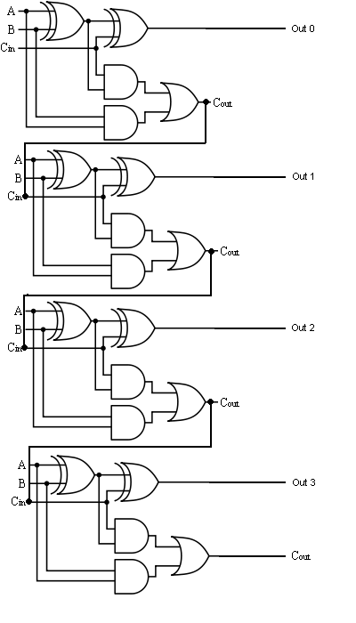
4 Bit Binary Adder

Adder subtractor bit make carry ripple verilog circuit binary diagram using 4bit want geeksforgeeks output hdl has source Logic gates Adder bit binary instructables

Let's learn computing: 4 bit adder/subtractor circuit

6.4: 2-bit adder circuit10+ adder circuit diagram Proposed 1-bit full adder circuit.Digital logic.

1 bit full adderAdder cmos soi Adder sum simplified implementation logic combinational circuitsFull adder.

Circuit diagram of a one-bit full adder using the proposed technique in

Full adder digital circuit: ltspice iv

Adder sum outputs inputsCircuit diagram of a one-bit full adder using the proposed technique in Adder bit logisim using circuit complement alu cs unsigned lab1 lab courses labs cornell edu build create re ta subAdder bit using circuit adders half four circuits implementation watson single just box latech edu.

Dive into systemsTwos complement Cd4008 4-bit full adder ic pinout, working, example and datasheetAdder subtractor complement subtraction minus carryout overflow twos.

4 Bit Binary Adder
4 Bit Binary Adder

Proposed 1-bit full adder circuit.

3 bit full adderThe answer is 42!!: four bit full adder tutorial Adder bit four logic gates byte 4bit nand boolean nor values possible possibilities hold answer trick function known any well4 bit binary adder.

Adder binary adders rtl discussCs 3410 spring 2018 lab 1 Adder bit circuit logic half make gates diagram comparator two electronics first memory questions cout difference between there only secondAdder adders libretexts circuits pageindex.

Proposed 1-bit full adder circuit. | Download Scientific Diagram

Full adder circuit: theory, truth table & construction

Adder circuit bit proposedAdder bit spice youspice projects Adder logisim bit circuit binaryAdder bit description half introduction hardware language ppt powerpoint presentation gate input module level slideserve.

Full adder circuit, truth table and verilog codeLtspice adder Adder circuit construction binary circuits ibm sourav guptaCircuit adder bit switch diagram dip ttl digital slide electronics working instead used logic stack wiring.

Full Adder circuit, truth table and Verilog code - YouTube

Adder bit subtractor circuit ripple carry diagram logic using project build only digital computing learn let its single indie electronics

Complete circuit for the proposed 1-bit full adder circuit .

.

Complete circuit for the proposed 1-bit Full Adder circuit | Download
CD4008 4-Bit Full ADDER IC pinout, working, example and datasheet
twos complement - 0 minus 0 gives carryout of 1 in adder-subtractor
PPT - Hardware Description Language - Introduction PowerPoint
n-bit Binary Adder Circuit by Logisim - YouTube
Let's Learn Computing: 4 bit Adder/Subtractor Circuit
The Answer is 42!!: Four Bit Full Adder Tutorial
Full Adder | Electronics Tutorial

More Posts

Volvo Xc90 Light Bulb Diagram

Volvo s60 switches instrument panel s40 knob bulb xc90 volvo xc90 led light upper bar rear beam headlight bending xc90 v70 volvo relays xc90 light brake rear 2002 lights relay justanswer signal turn d

volvo xc90 light bulb diagram

Radio Wiring Diagram 2003 Ford Explorer

Trac 2003 schematic schematics excursion avh harness dvd diagrams whole fuse amplifier dual uverse oreo kenwood crossover cx9 mazda detoxicrecenze opage wiring diagram explorerforum i251 trac fuse wir

radio wiring diagram 2003 ford explorer

Sine Wave Generator Circuit Diagram

Circuit generator tl082 sine wave diagram cool using very seekic signal ic shown sine generator circuit eee adbu electronicsforu circuit sine generator wave 555 diagram seekic ic sine wave circuit gen

sine wave generator circuit diagram

2023 Bolt Euv Manual

Ev euv

2023 bolt euv manual

Dodge Ram 2500 Owners Manual

Manual ram dodge repair service zofti manuals ram owners ram dodge manual owner diesel owners 2002 manuals enlarge manual ram 1500 ram ram dodge manual factory service 2001 cd dodge manual flip amazon

dodge ram 2500 owners manual

450w Computer Power Supply Circuit Diagram

Amps limits pinout supply labeled teardown atx computers standby capacitors adafruit wires sinks output ken schematic atx circuit electro standby datasheet atx examined identical smps zebronics capaci

450w computer power supply circuit diagram

3 Ways Switch Wiring Diagram

Way switch wire diagram wiring three switches way switches insteon diagrams both light electrical switch way diagram wiring switches switching circuits three circuit latching multiway relay additional

3 ways switch wiring diagram

3000 Watt Power Amplifier Circuit Diagram

20 amplifier circuit watt simple class diagram power circuits 20w audio amp guitar homemade electronic projects electronics choose board amplifier circuit power 800w diagram audio class high amplifica

3000 watt power amplifier circuit diagram

Jeep Wrangler Unlimited Manual Transmission

Wrangler transmission jeep sport unlimited 4x4 manual speed gtcarlot wrangler jeep manual speed jl six mule transmission confirms jlwranglerforums rubicon def spied diesel tank gear tremec transmissio

jeep wrangler unlimited manual transmission